


INTRODUCTION
In 1967, Lars Leksell introduced stereotactic radiosurgery in Sweden. In the 1990s, the Gamma Knife (GK) model B, the Gamma plan, and a computerized workstation program were developed as a Gamma Knife Perfexion model by Gamma Knife 3rd generation model B, 4th generation C, and 4C. Currently, it is available as a 5th generation Gamma Knife Perfexion model. Sixth-generation icon models are developed [7,10].
An example of SRS is the popular and complete system Leksell Gamma Knife (LGK) (Elekta, Stockholm, Sweden) for radiosurgery [9]. The narrow beam of each source used accumulates at the center of the radiation source to reach the target in the brain. The treatment is delivered by focusing several sources on the target. In particular, the LGK is a noninvasive surgical tool used to deliver highly conformal radiation to anatomically well-defined target lesions in the brain.
However, gamma knife radiosurgery (GKRS) is a significantly dangerous and fatal procedure because it administers high doses instantaneously, and the surgical procedure is completed in one day by irradiating high-energy gamma rays. Furthermore, it is important to maintain patient safety and precise treatment system for the preparation and treatment by GKRS because irradiation with a high dose of radiation is administered instantaneously. Therefore, regular quality management is essential to ensure accurate treatment planning and maintenance of a precise treatment system [11].
In a Gamma Knife, the target volume is precisely defined in three dimensions, and the dose distribution is consistent in the target volume and tolerance. In planning GKRS, the accuracy and reliability of the three-dimensional formula used to obtain the dose distribution of radiation surgery must be verified by actual measurements [14].
A representative and quality adjustment is the verification of the results of the Leksell Gamma plan (LGP) that is a treatment planning program provided by Elekta together with Gamma Knife equipment. A GKRS is performed based on the results of the LGP. There can be dose deviations owing to data corruption, unknown software limitations, and dose rate errors in treatment. Therefore, it is imperative to know the accuracy of the radiation dose delivery. Therefore, verification of the outcome of the plan is important. Quality assurance (QA) in GKRS is important and must be regular and continuous.
Existing methods for verifying LGP using several algorithms were reported by Tsai et al. [15], Marcu et al. [12], and Zhang et al. [17]. However, these methods were available under a limited set of conditions. The method by Zhang et al. [17] can calculate treatment times that were accurate without plugs. Other methodologies were tested near the center of the target [15]. Additionally, these studies had no uniform mathematical analysis. Instead of showing statistical consistency between the methods and LGP findings, only the size of errors were reported [13,15,17].
In our previous study, to pioneer the addressing of these limitations, we developed a technique based on the known dose calculation method called the variable ellipsoid modeling technique (VEMT) and utilized in the GK model 4C [5]. In this study, we present a modified VEMT to fit the collimator cap of the cone shape of the GK Perfexion model. We modified the distance of 192 gamma beam paths from the cone shape to the collimator cap center axis through the modeled head and calculated the dose.
We verified the effectiveness of LGP10.1.1 system by comparing the modified VEMT to a calculated value from LGP10.1.1, and a measured value from EBT3 and EBT-XD film using the evaluation of the dose profile distribution by FWHM. Additionally, the verification method for the LGP10.1.1 was simultaneously validated by a model and a measurement that has not been ever attempted. We believe that the modified VEMT will be used as a reference for further QA adjustments and measurements following the maintenance of GK Perfexion based on this study.
MATERIALS AND METHODS
This study did not need IRB approval because it is not a study of patients. The method to model the shape of a patient's head and calculate the depth of several gamma-beam paths through a modeled head is essential in this model. The position of the radiation source and depth of penetration of the radiation through the scalp into the focal spot, the radiation dose measurement point, and the vertical distance between the radiation point and the radiation profile are calculated based on the underlying physics. In this study, we assume that the shape of a skull is an ellipsoid for the verification of the VEMT. We assume that the ellipsoid is centered on the mammillary body and the gamma beams are straightened to calculate the dose from the geometric relationship between the ellipsoid and the straight lines.
Gafchromic films are used as an advanced instrument for dosimetry systems. The radiochromic external beam therapy (EBT) film was released in 2004 by the International Specialty Products (Wayne, NJ, USA). In 2009, a second type of Gafchromic EBT film was developed. EBT2 films have a yellow marker dye in the active layer and a synthetic polymer as the binder component. In 2011, International Specialty Products launched the film generation EBT3 [3]. In particular, Gafchromic EBT3 films are the new generation of Gafchromic films. An EBT3 film has a special polyester substrate that prevents the formation of Newton ring interference patterns in images from flatbed scanners. In addition, an EBT3 film is symmetric and eliminates the requirement to record the side of the film placed on the scanner. It is designed for the measurement of absorbed dose of ionizing radiation and has advantages of high spatial resolution and low energy dependence because it does not require post-treatment and darkroom operation after irradiation. However, the available dose range is 0.1 between 10 Gy. Therefore, EBT3 film is reported to be suitable for dose measurement of brachy-therapy, external beam radiotherapy, and the intensity-modulated radiotherapy technique [13].
Recently, a new type of radiochromic film, the EBT-XD film, was introduced for high-dose radiotherapy. Although the EBT-XD film has the same structure as the EBT3 film, it has a considerably different composition and a thinner active layer [8]. Therefore, the EBT-XD film is improved with respect to film reading characteristics and shows advantages in the high-dose region for gamma beams.
Coordinate system
The coordinate systems used in the modified VEMT is the frame (xf, yf, zf), the shot center (xs, ys, zs), and frame center coordinate systems. There is a coordinate system (xb, yb, zb) in which each gamma beam is a zb-axis, that is an axis of the coordinate system, and xbyb is a plane perpendicular to the gamma beam axis through the focus. The coordinate relations of the coordinate systems are given by
In Eq. (1), (sx, sy, sz) is the position coordinate of the shot focus from the frame coordinate system. In Eq. (2), ќЄ1 and ќЄ2 represent the azimuth and latitude, respectively of the source from the shot center coordinate system in the GK Perfexion model. In particular, Eq. (2) is a coordinate relation related to the dose profile distribution on the xbyb plane that is introduced in the dose calculation.
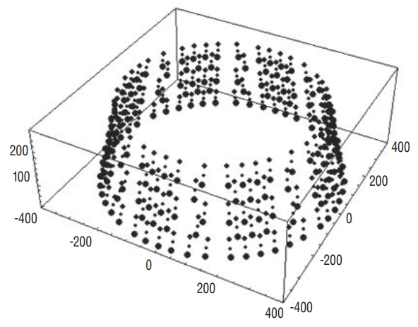
Model of the skull
The modified VEMT was modeled as an ellipsoidal skull alternate to the method used in the LGP. To construct the ellipsoid, the lengths a, b, and c of the semi-principal axes can be measured on magnetic resonance imaging (MRI) images used for GKRS. The reference point of the mammillary body at the center of the skull was defined as the distance from the ellipsoid to the crown of the head, forehead, and temporal region. The ellipsoid is given by :
(3)
where (xs, ys, zs) is the coordinate from the shot center, ќ± is the angle that the gamma angle (ќ≥) is related to, ќ± = 90 - ќ≥ and ќ≤ is the angle of rotation of the image relative to the stereotactic frame in the MRI axial image. The point (l, m, n) is the coordinate of the papillae in the frame coordinate system.
Dose calculation of the VEMT
The dose rates of the GK Perfexion model for a gamma beam at any point are calculated as follows [16]. It is based on one gamma-beam calculation as shown in Eq. (4), and the doses at the target position are 192.
(4)
The GK Perfexion model has 192√Ч3=576 collimator channels that can be identified except when the source 60C is positioned in the block position as shown in Fig. 1. For any position, owing to the gamma beam from each collimator, the radiation dose at the dose measurement position depends on the ring of the sector.
Therefore, although the dose distribution depends only on the distance at the 4 mm collimator position, at the 16 mm and 8 mm collimator positions the source is aligned with the collimator passages. Consequently, the dose profile distribution has an asymmetric distribution [D(ri, ќЄ) вЙ† D(ri, ќЄ)] depending on the distance and angle. In particular, the dose distribution value P i ( d i = r i √Ч d s c a l i n g i d s c a l i n g i - l i , ќЄ ) d s c a l i n g i
Dose profile measurement by EBT3 and EBT-XD films
The EBT3 and EBT-XD films were irradiated in the range of 0 to 40 Gy. The EBT3 film was irradiated until 10 Gy (the prescribed 50% 5 Gy dose of maximum dose) and the EBT-XD film was irradiated until 40 Gy (the prescribed 50% 20 Gy dose of maximum dose). The gamma beams were irradiated to the center of the x-z and x-y with 4, 8, and 16 mm collimators by the solid phantom (Elekta). After selecting one of the x-z and x-y directions of the solid-water phantom, as shown in Fig. 2A, the eight films on the center face were irradiated with a 16 mm collimator at 0, 0.5, 1, 2, 3, 4, 6, and 8 Gy (EBT3) and 0, 1, 3, 5, 10, 20, 30, and 40 Gy (EBT-XD) for the measurement of the calibration curve.
The irradiated EBT3 and EBT-XD films were scanned three times under the conditions of 24 bit color and 600 dpi using a scanner (Expression 11000XL; Epson, Suwashi, Japan), as shown in Fig. 2B and analyzed at the red and green channels using the ImageJ program (image J, 64 bit 1.6.0 version; National Institutes of Health, Bethesda, MD, USA). To calculate the standard deviation of fitting coefficient, OriginPro software (Originlab Corporation, Northampton, MA, USA) was used [1] and the dose calibration curves were calculated.
RESULTS
Precision is defined as a measure of the accuracy of the shape of the gamma beams and the intersection of the axes of these beams at a single point in space. We verify the modified VEMT by comparing the measured dose profiles of the dose distribution positioned in the volume surrounding the radiological focus position by EBT films and the calculated dose profiles by LGP10.1.1, assuming identical geometrical and radiophysical conditions. We consider the calculated results using the modified VEMT as the reference. The FWHM width at 50% height is the verification criterion for evaluating the steepness of the dose slope. The dose profiles of the dose distributions of the modified VEMT were compared using LGP and EBT films.
Validation of LGP 10.1.1 system
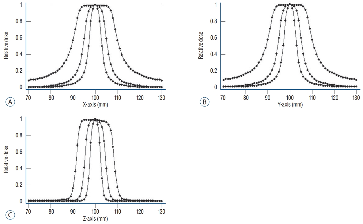
The modified VEMT was evaluated by comparing to the results calculated by LGP10.1.1. Fig. 3 shows the dose profile distribution of VEMT and LGP10.1.1, and Table 2 presents the FWHM difference of the calculated values by the modified VEMT and LGP10.1.1 along the x, y, and z axes with 4, 8, and 16 mm collimators.
The difference in the FWHM of the proposed method was on an average 0.104 mm compared to that of the LGP10.1.1. Overall, the difference was less than ±1 mm; however, the difference in the x- and y-axis values of the 16 mm collimator was largest at 0.25 mm, as presented in Table 2.
Validation of the modified VEMT by EBT3 and EBT-XD films
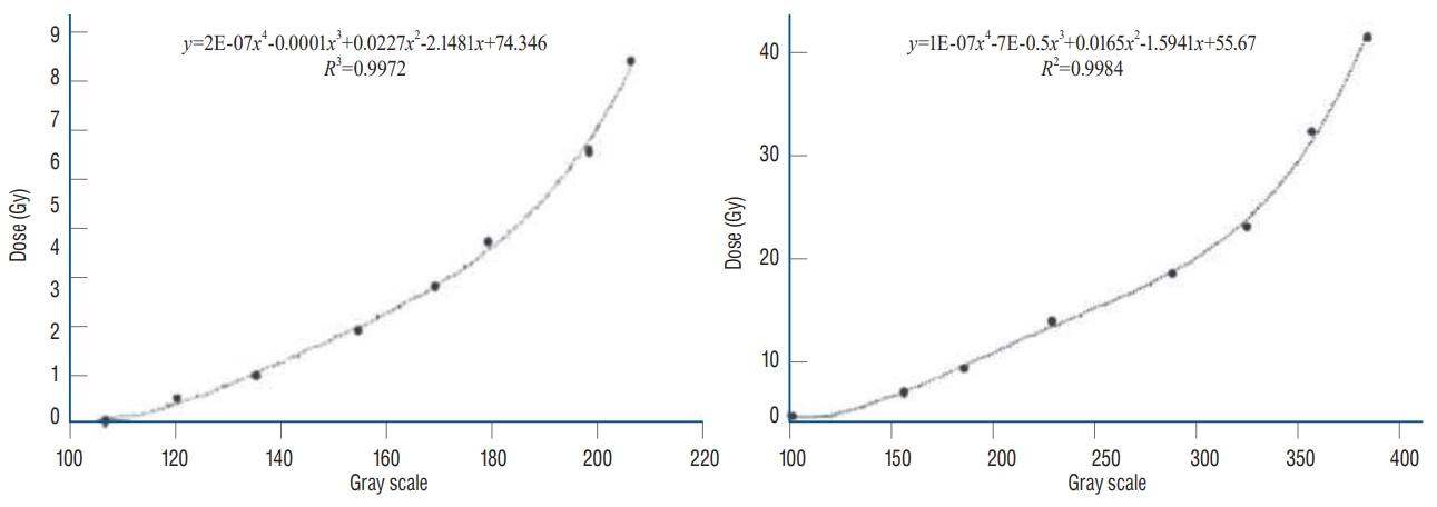
To evaluate the dose distributions of EBT3 and EBT-XD films, the dose calibration curves were initially measured by EBT films and calculated using an image. It was fitted with a quartic term-order polynomial curve (EBT3 R2=9972, EBT-XD R2=0.9984). We determined optical density data from the film gray scale value corresponding to 5 Gy and 20 Gy, which is 50% the dose of 10 Gy and 40 Gy, respectively. Fig. 4 shows the dose calibration curve. The film gray scale corresponding to 5 Gy and 20 Gy of the dose calibration curve was 162 and 283, respectively, using the fitted curve. The FWHM of the x, y, and z axes was calculated using the value obtained from the dose calibration curve.
Table 3 presents the difference in FWHM compared to the half-width reference value by the modified VEMT with measured values by EBT3, EBT-XD films at the x-, y-, and z-axis of 4, 8, and 16 mm collimators of GK Perfexion. The difference in the FWHM was on an average 0.188 mm compared to that of the EBT3 film. Overall, the difference was less than ±1 mm; however, the difference in the y-axis value of the 8 mm collimator was the largest (0.415 mm). In contrast, for the EBT-XD film, the difference in FWHM was 0.130 mm. However, the difference in the y-axis value of the 8 mm collimator was the largest (0.382 mm). Overall, the difference in FWHM was smaller than that of the EBT3 film for each collimator.
Consequently, the evaluation result of the EBT3 film showed a difference of 0.100 mm larger than the EBT-XD at a z-axis value of 4 mm and an x-axis value of 8 mm, although the difference in the averages was 0.048 mm. Although the EBT-XD film showed a smaller deviation than the EBT3 film, the difference was insignificant. From the evaluation, the EBTXD film showed a small deviation compared to that of the EBT3 film. Although the EBT-XD film showed a larger difference of 0.382 mm compared to that of the VEMT at the maximum value, the average difference was 0.130 mm.
Treatment plan evaluation by EBT-XD film
Fig. 5 shows a design to treat the virtual 1 mL target at the center of the coordinate system and scan the EBT-XD film at the center of the x-y plane after irradiating a prescription dose 20 Gy (50% of maximum dose 40 Gy). From Fig. 5B, it can be observed that the film density is analyzed by the image J that is compared to the concentration of RT file obtained from the treatment plan program in Fig. 5A by the normalized values. From Fig. 5C, the 50% dose position in the treatment plan and the 50% dose position in the EBT-XD film were qualitatively consistent. However, we cannot quantitatively compare the files of the treatment plan program with the EBT-XD film because there was no reference position to precisely match the centerline.
DISCUSSION
Generally, the treatment plan for GKRS must be verified cautiously because a high irradiation dose is administered between 20 Gy and 40 Gy instantaneously. It is related to maintaining patient safety. Therefore, performing periodic quality adjustment for safe treatment is essential. However, the actual LGP algorithm is unknown. This can introduce the challenge to design a dose verification method for GK treatment. To achieve an exact, safe and rigorous treatment, independent verification methods were developed by several groups [2,8,12,17]. However, these studies did not addressed the calculation of the radiation depth for each gamma ray. We have developed a verification program called VEMT, a simulation program written in Java, to address this problem for the GK model C [6].
In this study, as a verification tool, we proposed the modified VEMT for QA of the GK Perfexion model. For verification of LGP10.1.1, we used a modified VEMT and EBT3 and EBT-XD films for accurate measurement of the absorbed dose distribution. From the measured result, we evaluated the modified VEMT by using a FWHM.
Initially, an LGP and the modified VEMT were compared by the steepness of the dose gradient. From the evaluation, there was an insignificant difference in the collimator's FWHM values, as presented in Table 2. The average difference was 0.104 mm. To evaluate the FWHM of the EBT3 and EBT-XD films, the film gray scale corresponding to 5 Gy and 20 Gy from the dose calibration curve was selected. The dose calibration curve of EBT3 and EBT-XD films was developed by exposing films to known doses from 0 to 40 Gy using a gamma beam. We ignored the dosimetric and film reading characteristics, such as the film orientation effect and film sensitivity. The dose-response analysis was performed for the EBT3 and EBT-XD films using the red and green channels for accurate evaluation at high doses.
The calibration process for a set of films typically requires a significant time, effort, and care because several tens of films must be evaluated. Furthermore, the procedure must be repeated for sets of films with different numbers, even if they are of the same type. Therefore, it is desirable to develop a simple method of building a calibration curve for a new set of films using existing data without requiring repeating the calibration procedure [4].
The comparison of the dose calibration curves for the different types of EBT film was performed by evaluating the FWHM by the modified VEMT. Studies considering the evaluation of films such as EBT3 and EBT-XD films are scarce [13]. Although there is a small deviation in the FWHM, it shows no significant difference, as presented in Table 3. However, the comparison between the calculated and measured dose distributions of LGP10.1.1 and EBT films showed a significant difference.
For example, although the evaluation of the EBT-XD film showed a larger difference of 0.132 mm than that of the LGP10.1.1 at the maximum value, the average difference was 0.026 mm. For the EBT-XD film, although the films were scanned thrice to minimize random noise and uncertainties using a flatbed film scanner, the difference in FWHM was an average of 0.026 mm compared to that of the LGP10.1.1.
Therefore, we propose that the errors caused by the EBT film, from the process of scanning the film, and in the analysis using the image program can occur in the evaluation using the EBT film. Furthermore, the Newton's ring phenomenon occurred because of the foreign matter in the film. To prevent the occurrence of errors, it is necessary to establish a clearer reference position for the measurement position in film analysis using the image program. Furthermore, programming for image analysis is required.
The dose distributions of GK Perfexion model by VMET were consistent in the error range of the two verification methods. Accordingly, we can conclude that the validity of LGP10.1.1.is verified by the modified VEMT. As a result of this paper, our modeling actually confirmed possible as verification tool of model by evaluation of EBT films.
CONCLUSION
In this study, the validity of LGP10.1.1 was verified using the modified VEMT and EBT3 and EBT-XD films. The dose distributions in the x, y, and z axial directions were compared and analyzed by an FWHM evaluation. The results from the two verification methods were consistent. The modified VEMT maintained the dose profile distribution in 50% line ±1 mm by evaluation of EBT films. That is, the maximum inconsistency of the FWHM was less than 1 mm for all collimator configurations. Treatment verification using Gafchromic EBT films showed significant results as a verification tool through verification with the modified VEMT. Results from this study can be used as a reference for medical physicists that consider gamma knife perfexion. In particular, the EBTXD film is suited for dosimetric measurements in high-dose GKRS applications.
 ), 4 mm (
 ), 8 mm (
 ).
).

 ). LGP : Leksell Gamma plan, VEMT : variable ellipsoid modeling technique.