


INTRODUCTION
Deep brain stimulation (DBS) is an established procedure for disabling movement disorders or intractable pain. Despite technical advances and advances in neurostimulation devices in DBS procedures, many problems have been observed with this system in patients, especially hardware-related complications including skin infection or erosion, lead fracture, migration of the devices, and hardware malfunctions2,4,7,8,11,14,15,16). Hardware-related complications have been frequently reported, with the incidence ranging from 2.7% to 50%13). The wide variation in reported DBS adverse event rates has been attributed to the variable level of experience among implanting centers4). The connectors used for DBS implants sometimes cause a problem in patients with thin scalps8,14). Scalp erosion and infection related to the bulky connector may be associated with differences at the implanted site and in the technique used to secure the connector. Commonly, the standard technique has been performed to secure the lead-extension connector, which is placed on the cranial surface1,8,10,12). Some neurosurgeons have attempted to drill a trough or a groove in the cranial surface to decrease the profile of the connector3,5,8,14). However, little information is available regarding the detailed method and long-term outcomes in the securing technique of DBS connectors. We describe a groove technique for securing an electrode connector in DBS surgery and evaluate the long-term outcomes of electrode connector-related complications of the standard technique compared with those of the groove technique in patients undergoing DBS.
MATERIALS AND METHODS
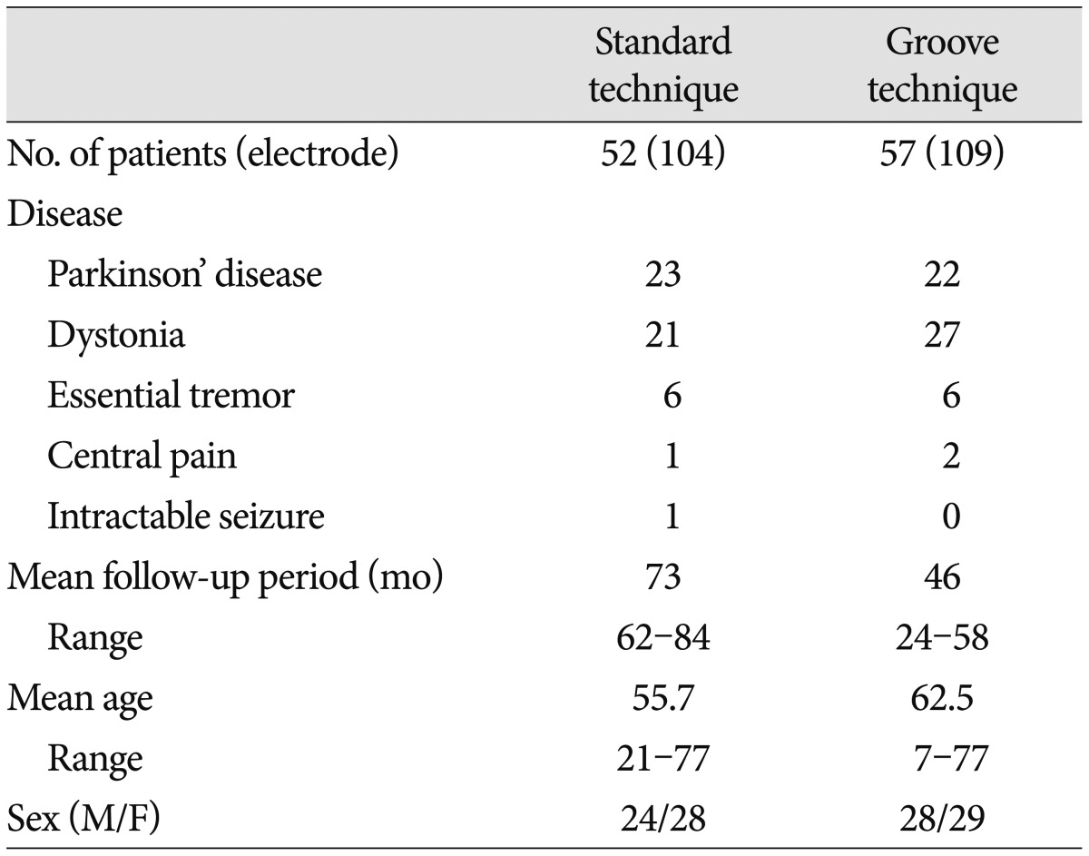
We retrospectively analyzed electrode connector-related complications in patients whose DBS was undertaken by a single neurosurgeon from 2005 to 2011. DBS electrode implants were performed in 112 patients with Parkinson's disease, dystonia, essential tremor, pain, or seizure. Three patients were excluded : One patient with severely disabling dystonia died of pneumonia on follow-up 8 months after surgery, one with Parkinson's disease was removed from DBS electrodes because of intracerebral hemorrhage, and one with dystonia was lost to follow-up. The remaining 109 patients (Table 1) with follow-up information of more than 24 months were evaluated, either by reviewing their medical records or by telephone interviews. Patients were divided into two groups by surgical techniques for securing an electrode connector during DBS surgery, regardless of their disease. In the standard technique, an electrode connector was placed on the vertex of the cranial surface. The standard group included 52 patients (104 electrodes) treated by the standard technique from January 2005 to December 2007. In the groove technique, an electrode connector was implanted in a groove or a trough in the posterior part of the parietal bone below the parietal eminence. The groove technique group included 57 patients (109 electrodes) treated by the groove technique from January 2008 to March 2011. We implanted Soletra pulse generators (Model 7426), and extension kits (Model 7482) (Medtronic, Inc., Minneapolis, MN, USA). The diameter of the extension leads was 2.8 mm, the diameter of the connectors was 4.06 mm, and the length of the connectors was 30 mm. A connector boot was placed over the connection and tied to exclude fluid. The total length of the connector with the boot was approximately 4 cm. We used cylindrical boots for the groove technique and cylindrical or winged boots for the standard technique. The two groups were compared in terms of wound erosion or infection, as well as migration related to the connector. A post-operative skull X-ray was obtained to evaluate the location of the connectors and to rule out complications.
We used the chi-square test to investigate the efficacy of this technique. Analysis of the results was performed using the Statistical Package for the Social Sciences (SPSS) software (ver. 12.0; SPSS Inc., Chicago, IL, USA). A p value less than 0.05 was considered statistically significant.
Operative procedure
To implant the DBS electrode or lead (Model 3389 or 3387; Medtronic, Inc. Minneapolis, MN, USA), the skin incision was made in a straight vertical or a curved fashion approximately 5-7 cm in length, with consideration given to a frontal burr hole. After the electrode implantation at a target site, the electrode was fixed to the cranium with a Medtronic silicon burr-hole ring and cap or a miniplate. The electrode was externalized routinely for a trial of stimulation for 2-6 days. The proximal end of the electrode was connected to a percutaneous extension connector and a Medtronic 7495 external cable. A subgaleal dissection was performed around the burr hole, especially toward the parietal area, near the incision. The external cable exited the skin through a stab incision away from the primary skin incision by use of a Med-tronic kit for an external cable. The excess electrode line and connector were placed in the subgaleal space. The scalp incision was then closed layer by layer.
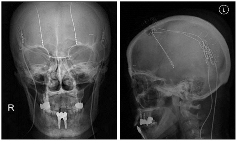
To implant the neurostimulator, called the implantable pulse generator (IPG), the patient was placed in the supine position while under general anesthesia, and the patient's head was turned fully toward the opposite side. The patient's trunk was extended with support cushions under the shoulders to provide as straight a line as possible from the connector incision to the neurostimulator incision. A 6-cm horizontal incision was made roughly two fingerbreadths below the clavicle, and a subcutaneous pocket was fashioned. To remove the percutaneous extension, we cut off the external segment of the percutaneous extension from where it exits the skin and reopened the scalp incision near the burr hole. The proximal DBS lead and temporary connector were withdrawn carefully from this skin incision, and the old boot and connector were discarded. In the standard technique, a 2-cm incision was made around the parietal eminence. At this point, a subcutaneous tunnel was made from this incision site down to an infraclavicular subcutaneous pocket for IPG by use of a Medtronic DBS tunneling accessory kit. An intermediate incision at the retroauricular area was required in cases with resistance against the parieto-occipital tunnel. Next, the extension cable was passed retrograde from infraclavicular to scalp incisions. The proximal end of the electrode was connected to the extension connector. A connector boot was covered over the connector and tied with Mersilk 4-0 (Ethicon Inc., Lenneke Mareiaan, Belgium). The connector was delivered from the primary incision site near the burr hole to the vertex of the parietal bone using a subcutaneous tunnel through the subgaleal layer. The excess electrode was left in the subgaleal pocket. We anchored the connector or extension line to the fascia or periosteum with a nonabsorbable suture. In the groove technique, a pathway from a connector point (namely, C point; 4-5 cm posterior and superior to the pinna) of the posterior parietal area (Fig. 1) starting at the parietal eminence to the infraclavicular region was marked on the skin. A linear skin incision was made about 6 cm long at the C point in the direction of the lead passage from the parietal eminence to 4-5 cm posterior to the pinna. The fascia and muscle were opened longitudinal, and then the periosteum was dissected using a periosteal elevator. We drilled and made a groove or a trough (about 4 cm long, 8 mm wide, and 5 mm deep) (Fig. 2A), depending on the shape and size of the cylindrical boot and the connector, along the C point below the parietal eminence. At this point, a subcutaneous tunnel was made from the incision site of the posterior parietal area to the IPG pocket. After the IPG was secured, we connected the DBS lead to the extension and placed the profile of the connector with an excess lead line within the groove. Nonabsorbable silk, anchored at the miniholes of the groove margin, was fastened to the opposite holes (Fig. 2B). The fascia was closed with Vicryl 2.0 to approximate the muscle and fascia over the connector. The skin was then closed with sutures or staples.
RESULTS
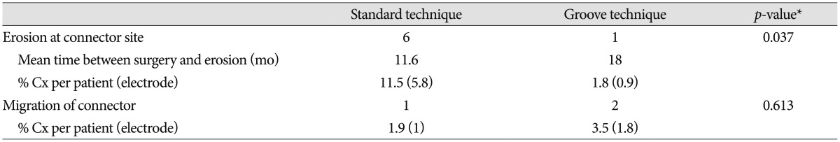
The mean follow-up period was 73 months (range, 62-84 months) in the standard technique group and 46 months (range, 24-58 months) in the groove technique group. The mean age was 55.7 years (range, 21-77 years) in the standard technique group and 62.5 years (range, 7-77 years) in the groove technique group. Basic demographic data, including the number of patients, the number of electrodes, mean age, and sex are listed in Table 1. No severe complications occurred with the groove technique, and the connector was hardly noticeable. The groove technique did not impinge on wearing glasses or lying down. There were 10 (4.7%) connector-related complications in 233 electrodes and 10 (9.2%) connector-related complications in 107 patients (Table 2). There were seven (3.3%) cases of wound erosion and three (1.4%) cases of connector migration per electrode. Wound erosion per electrode at the connector site was experienced by one patient (0.9%) with the groove technique and six patients (5.8%) with standard technique. This difference was statistically significant (chi-square test, p=0.037). The erosion in the groove technique occurred in a patient with truncal dystonia with retrocollis and psychiatric problems who came from a poor socioeconomic background. The mean time between wound erosion and DBS surgery was 11.6 months for the standard technique and 18 months for the groove technique. Each one erosion patient with the groove technique and the standard technique was successfully treated with surgical debridement. Five patients with wound erosion in the standard technique group needed additional management, including replacement of hardware (three cases). Migration of the connectors occurred at one (1%) electrode with the standard technique and at two (1.8%) electrodes with the groove technique but did not need surgical intervention. There was no significant difference in migration between the techniques (chi-square test, p=0.613).
DISCUSSION
In this study, we found that the technique for securing the connector by creating a trough in the cranial bone provided a statistically significant decrease in connector-related complications, such as skin erosion and infection compared with the standard technique in which the connector is placed on the cranial surface. The results from the standard technique in this study corresponds to the results of a Toronto team8) who reported a connector-related complication rate per electrode of 6.5%. In their report of the hardware-related complications of DBS, the connector was the most common source of skin infections or erosion complications, followed by the burr hole and the pulse generator. Various techniques and devices have been used to implant an electrode connector for DBS. The introduction of an extension connector with a lower profile has significantly reduced erosion incidence1,8,12). The connector usually is located on the parietal bone, parieto-occipital bone, or top portion of the frontal bone, or in the mastoid area, not in the cervical area14). Connector migration is less likely to occur on the vertex area than on these other sites. In this study, the occurrence of adverse migration of the connector was not significantly different between the standard technique group and the groove technique group, although the connectors were implanted in different sites. To avoid distal migration of the connector, it must be anchored to the skull or the fascia. In the groove method, it is also helpful to hold the connector in place with a tie or a miniplate. Infections at the site of the connector may be related to wound erosion and present at variable times after implantation1,8,14). The rate of published hardware-related adverse events, which increases with the length of follow-up, may be as high as 27%9). Wound erosion may occur in a delayed fashion. In one study, device-related infections presenting later than 6 months were clearly associated with wound erosion after a perioperative period of normal wound healing15). To prevent posterior scalp erosion at the connection site, the connector should be secured deep in the subcutaneous tissues and not in the relatively thin scalp area10). A previous study used a similar site for connector implantation as described in our study (i.e., making a groove in the parietal bone below the parietal eminence)8). In the groove technique, the posterior parietal area has several advantages compared with the vertex. It has a relatively thicker scalp coverage area and is farther from the burr hole site than the vertex area. The distributed arrangement of connector locations may reduce the likelihood of hardware-related infections or of extensive infections spreading along the lead. In cases with localized infection related to only one hardware device, partial removal of the hardware can be successfully used15). The site for the groove technique has a greater chance of contact during sleeping or wearing glasses than the vertex area, but it was found to be relatively safe in our cases. Without making a new skin incision, it is easy to tunnel through subcutaneous tissue from the posterior parietal area to the infraclavicular region. Some authors have suggested that the groove procedure may be more invasive and time-consuming than the standard procedure6). However, because connector-related complications can be avoided to a great extent with the groove technique, the simple expenditure of time and effort in this regard is well worthwhile. In this study, we demonstrated that securing DBS connectors by making a groove or a trough in the skull decreased the risk of complications in almost all cases.
CONCLUSION
Hardware-related complications associated with the connector may occur in DBS procedures. Such complications need to be prevented. The groove technique, which involves securing an electrode connector using a groove or a trough in the cranial bone at the posterior parietal area, offers an effective and safe method to avoid electrode connector-related complications, such as skin erosion, infection, and connector migration during DBS surgery.