The Mechanical Effect of Rod Contouring on Rod-Screw System Strength in Spine Fixation
Article information
Abstract
Objective
Rod-screw fixation systems are widely used for spinal instrumentation. Although many biomechanical studies on rod-screw systems have been carried out, but the effects of rod contouring on the construct strength is still not very well defined in the literature. This work examines the mechanical impact of straight, 20° kyphotic, and 20° lordotic rod contouring on rod-screw fixation systems, by forming a corpectomy model.
Methods
The corpectomy groups were prepared using ultra-high molecular weight polyethylene samples. Non-destructive loads were applied during flexion/extension and torsion testing. Spine-loading conditions were simulated by load subjections of 100 N with a velocity of 5 mm min-1, to ensure 8.4-Nm moment. For torsional loading, the corpectomy models were subjected to rotational displacement of 0.5° s-1 to an end point of 5.0°, in a torsion testing machine.
Results
Under both flexion and extension loading conditions the stiffness values for the lordotic rod-screw system were the highest. Under torsional loading conditions, the lordotic rod-screw system exhibited the highest torsional rigidity.
Conclusion
We concluded that the lordotic rod-screw system was the most rigid among the systems tested and the risk of rod and screw failure is much higher in the kyphotic rod-screw systems. Further biomechanical studies should be attempted to compare between different rod kyphotic angles to minimize the kyphotic rod failure rate and to offer a more stable and rigid rod-screw construct models for surgical application in the kyphotic vertebrae.
INTRODUCTION
The rod-screw based systems are now considered the gold standard systems for spinal fixation. Transpedicular screw fixation, which are considered excellent stabilizer for spine segments, has been used frequently in the management of many spinal disorders, including degenerative diseases, fractures, tumors, scoliosis and deformities through the posterior approach121422). These rigid rod-screw systems facilitate reduction and manipulation of many deformities via rod preoperative and in situ bending, rotation, distraction and compression. The primary target of rod-screw system fixation is to prevent instability till biological arthrodesis occur1122). Rod-screw system failure through screw pullout, screw breakage and rod breakage are frequently encountered during clinical practice. Although many biomechanical studies on transpedicular screw pullout and breakage have been performed128101722), but it is strange that, the literature is lacking of a well-structured biomechanical study enriching the knowledge regarding the effect of rod contouring (lordotic and kyphotic curvatures) on the strength of the rod-screw construct and the impact of such different curvatures on rod fatigue and then breakage. The aim of the present biomechanical work is to study the behavior of different rod curvatures against variable stresses to detect the effect of rod contouring (straight, kyphotic and lordotic) on rod fatigue which leads later on to breakage.
MATERIALS AND METHODS
Material model
The well-known ultra-high molecular-weight polyethylene (UHMWPE) samples were used to form three spine corpectomy model groups. UHMWPE blocks were preferred to be used in place of human bone, to avoid the biological differences of bone density. Many studies have reported the ability of using UHMWPE blocks to imitate corpectomy models as an approved method for mechanical evaluation of rod-screw systems stability20).
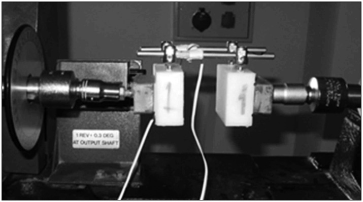
Eighteen corpectomy models were created to simulate a human spine model (Fig. 1). Three types of rod models were used : straight (n=6), 20° kyphotic (n=6), and 20° lordotic (n=6)5).

Rod-screw system used in the corpectomy model. Universal test machine used for flexion/extension and deformation testing. a-f : UHMWPE blocks, b : poly-axial screws, c : strain-gauge, d-e : fixation apparatus.
Instrumentation
In our study, 45 mm long poly-axial titanium, 5.5 mm thick pedicle screws and 110 mm long titanium rods (6.35 mm thick, TiAlV) (Tıpsan Medical Devices, Izmir, Turkey) were used. The two titanium rods were attached and secured to the poly-axial screws (Fig. 1). A fixed longitudinal gauge with a 76 mm of length was present between the vertebrae block models, flexion/extension and torsion apparatus was designed for simulating the corpectomy model2022). During our study, transverse connectors were not used, because earlier biomechanical studies have shown that transverse connectors do not effect compressive loading in mechanical tests8). The titanium rods in the corpectomy models were fitted with a strain-gauge (UFLK-2-11 type, 120 Ω, 2 mm long, Tokyo Sokki Kenkyujo, Japan) placed in the middle and on each one's longitudinal axis. Another set of strain-gauges were placed at the heads of the pedicle screws and the strain at the screw heads was measured, according to the method previously described in the literature121720).
The flexion loading of the lordotic and kyphotic rod-screw systems (Fig. 2) shows that, the anterior bending moment applied on the lordotic rod-screw systems is T1=F1×D1; while the bending moment applied on the kyphotic rod-screw systems is T2=F1×D2. Although the same force F1 is applied to both systems, because of the distance from the center, the resultant bending moment T2 of the kyphotic rod-screw system is larger than T1 of the lordotic system, as D2>D1.

Schematic illustration of the lordotic and kyphotic rod-screw systems. D1 and D2 show the difference of the moment arm; D2>D1.
Mechanical testing
The theoretical model of mechanical testing was accomplished using the well-known guidelines of ASTM F1717-04 "Static and Dynamic Test Method for Spinal Implant Assemblies in a Corpectomy Model" to evaluate the mechanical properties of the 6.5 mm rod under static and dynamic loading. Non-destructive load was applied during flexion/extension and torsion testing92022). In order to apply the load to the corpectomy models, a custom-made system was designed for the test machines. Flexion/extension tests were accomplished using an electromechanical universal testing machine (Shimadzu 5kN AG-X, Japan) (Fig. 1). To simulate spine-loading conditions, the samples were subjected to a load of 100 N to ensure an 8.4-Nm moment with a velocity of 5 mm min-1.722) To examine torsional loading, the UHMWPE blocks were mounted in a torsion testing machine (TecQuipment, Ltd., United Kingdom) and subjected to rotational displacement of 0.5° s-1 to an end point of 5.0° (Fig. 3)1920). The obtained data were analyzed using SPSS v.15. for Windows (SPSS Inc., Chicago, IL, USA). The non-parametric one-way analysis of variance was used for categorical comparisons. Statistical significance level was set at p<0.05.
A corpectomy model in the torsion testing machine.
RESULTS
Stiffness was recorded in all rod systems during application of deformation loads, lordotic rods had a mean stiffness value of 22.98 N mm-1, versus 12.82 N mm-1 for the straight rods. Statistical significance was detected between the mean stiffness values of both rod systems with p=0.001. The straight rods mean stiffness value was 44.2% less than that of the lordotic rods. The mean stiffness for the kyphotic rods was 17.19 N mm-1. Statistical significance was detected between the mean stiffness values of both rod systems with p=0.007. The kyphotic rods mean stiffness values was 25.1% less than that of the lordotic rods. Statistical significance was detected between the mean stiffness values of the kyphotic rods and the straight rods with p=0.02. The straight rods mean stiffness value was 25.4% less than that of the kyphotic rods (Fig. 4).
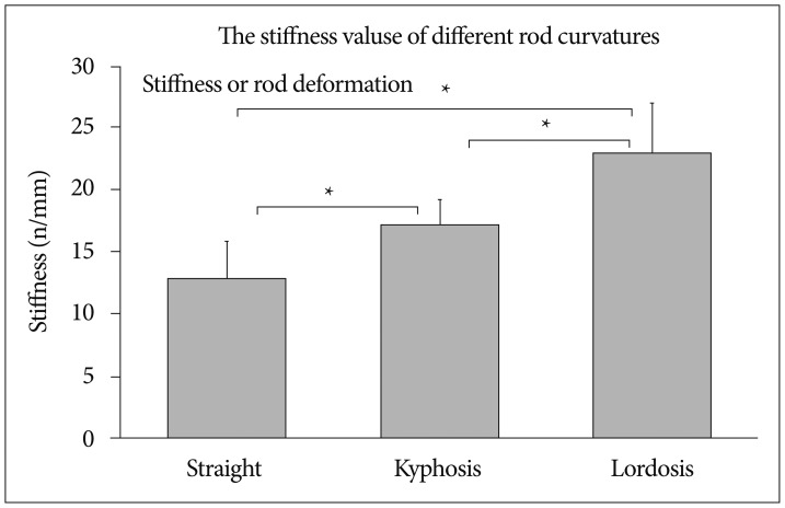
The stiffness values of different rod models.
Under extension conditions, the mean strain values for straight, kyphotic and lordotic rods were (1086 µε, 1244 µε, 1124 µε) respectively. Statistical significance was detected between the mean strain value of the kyphotic rods when compared to the straight and lordotic rods with p values of (0.006 and 0.004) respectively (Fig. 5).
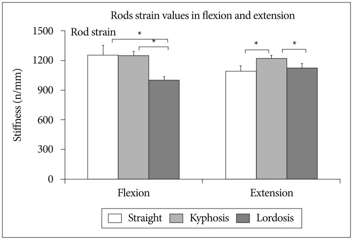
Rod strain values during flexion and extension.
Whereas the mean strain values measured from the heads of polyaxial screws in extension of the straight, kyphotic and lordotic rod-screw systems were (37 µε, 23 µε, 26 µε) respectively. Straight screw heads show the highest strain values during extension which is statistically significant when compared to kyphotic and lordotic heads with p values of (0.004, 0.006) respectively (Fig. 6).

Screws strain values of different rod curvatures during flexion and extension.
Under flexion conditions, the mean strain values for straight, kyphosis and lordotic rods were (1249 µε, 1244 µε, 1001 µε ) respectively. Statistical significance was detected between the mean strain value of the lordotic rods when compared to the kyphotic and straight rods with p values of (0.004 and 0.003) respectively. No statistical significance was detected between the kyphotic rods and the straight rods with a p value of 0.873.
Whereas the mean strain values measured from the heads of polyaxial screws in flexion of the straight, kyphotic and lordotic rod-screw systems were (18 µε, 33 µε, 31 µε) respectively. Straight screw heads demonstrate the lowest strain values during flexion, the difference is statistically significant when compared to kyphotic and lordotic heads with p values of (0.004, 0.006) respectively.
Under torsional conditions, the mean stiffness values for straight, kyphotic and lordotic rods were (2.55 Nm degree-1, 3.05 Nm degree-1, 3.25 Nm degree-1) respectively. Statistical significance was detected between the mean stiffness value of the straight rods when compared to that of the lordotic and kyphotic rods with p values of (0.025, 0.013) respectively. No statistical significance was detected between the kyphotic and the lordotic rods in torsional conditions with p value of 0.38 (Fig. 7).
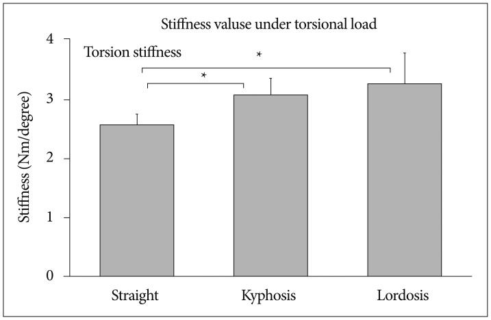
Rod-screw systems stiffness values under torsional load.
DISCUSSION
Many studies in the literature had documented that the strength of rod-screw system was mostly associated to the structural anatomic relationship between the size of the isthmus of the pedicle and the rod-screw diameter92122). The created model of corpectomy is considered as an extremely aggressive surgical scenario, due to the fact that, all loads are transmitted from the healthy segment proximally to the distal one completely through the rod-screw system12).
Many studies have used UHMWPE model as a corpectomy model. The model attempts to eliminate the variable biological differences of human vertebrae samples like size, bone density and shape22). Clinically the yield strength of a rod-screw system is more relevant than that of the ultimate strength. One of the main aims of any fixation system is to preserve the stability mainly in the sagittal plane. As it has been defined before, if the axial compressive loads exceed the yield strength of a system, an implant permanent deformation is likely to occur, resulting in a kyphotic deformity. Exceeding the implant ultimate strength is problematic and demonstrates a bad surgical application due to support absence of the spine anterior column. Any rod-screw system is designed to create stability in the spine during the healing period of bone grafting must be resistant to fatigue failure. It is estimated that 1 million cycles (approximately 4 months) is enough for fusion to take place171922). The aim of our study is two-fold; to detect the impact of rod curves on rod failure and to record the effect of such curves on the stress created upon the screw heads which leads to screw failure in the future.
The highest level of stiffness was observed in the lordotic rod-screw system. It was significantly higher than that of the straight rod-screw system (p=0.002) and that of the kyphotic rod system (p=0.004), indicating that the lordotic rod-screw system is the most stable and rigid system under static conditions without dynamic loading.
Under flexion conditions, lordotic rods show the least mean strain values when compared to that of the straight rods and that of the kyphotic rods with a significant statistical difference of p values (0.004 and 0.003) respectively. No statistical significance was detected between the kyphotic rods and the straight rods with p=0.873. This indicates that, lordotic rods are more resistant to flexion loadings when compared to straight and kyphotic rods.
Under flexion loading, the highest polyaxial screw head strain was observed in the kyphotic rod-screw system (33 µε) (Fig. 3). The strain on the screw heads of the straight rod-screw system was statistically lower than that of the kyphotic and lordotic rod-screw systems with p values of (0.004, 0.006) respectively. Based on these findings, we think that, screw failure especially in the kyphotic rod-screw system under flexion loading is more likely to occur. Chen et al., showed that pedicle screws commonly broke/fractured at the junction of the screw and the UHMWPE blocks48). Schroerlucke et al.15), showed that implant failure is more common in patients with increased kyphosis and increases with a line parallel to the degree of kyphosis. Rod failure is the most common rod-screw implant complication.
Under extension loading rod strain gauge measurements were 1244 µε in the kyphotic rods. Under extension loading, the strain of the kyphotic rod-screw system was significantly higher than that of the straight and lordotic rod-screw systems with p values of (0.006, 0.004) respectively. These findings show that the straight rod-screw system was the most rigid system under extension loading. Sun at al.18), showed that, supporting the pedicle screw with an infra-laminar hook enhances the stiffness of a construct by 21% in kyphosis. In thoracolumbar fusion surgery with rod-screw systems, failure rates ranged from 0.4% to 22%. In situ rod contouring and corrective surgeries using devices for reduction are considered as risk factor for the failure of pure titanium or titanium alloy made spinal constructs; due to their bending sensitivity61316). In rod-screw systems, if the mechanical properties of rod contouring are known, it may guide the surgeons to make a better choice for a more stable rod-screw constructs.
Under extension loading conditions, the strain occurring in the pedicle screw heads was measured. The highest screw strain (37 µε) was recorded for the straight rod-screw system, as compared to the lordotic rod-screw system (26 µε) and kyphotic rod-screw system (23 µε). It is thought that the likelihood of screw failure is high in the straight rod-screw system under extension loading.
In an artificial spine model, Belmont et al.3), demonstrated that, as kyphotic angle increased up to 27°, the strain of the rod increased by 27%. Our results are in line, because the mean kyphotic rod strain was 1244 µ and the mean lordotic rod strain was 1001 µ. The mean lordotic rod strain value was significantly lower than the strains in straight and kyphotic rod-screw systems (p=0.003 and p=0.004) respectively. Based on the strain values, the lordotic rod-screw system was the most rigid of the 3 systems, under flexion loading. This is expected, because D2 is greater than D1, as demonstrated in Fig. 2. Because of spine's natural shape, the application of kyphotic spine implants have larger bending distances than lordotic spine implants, i.e., D2>D1.
Under torsional loading conditions the lordotic rods system in the present study exhibited the greatest rotational rigidity (3.24 Nm degrees-1), followed by the kyphotic rod-screw and the straight rod-screw systems. Which show statistical significance with p values of (0.013 and 0.025) respectively (Fig. 4). The lordotic rod-screw system was the most rigid system of the 3 systems examined in the present study.
This study contains some limitations which can not be avoided like many other in-vitro biomechanical studies and this is due to the difficulty in resambeling the physiological conditions of a human spine without muscles and soft tissue which is well-known to increases the construct rigidity and the stability of the bone-implant interface.
CONCLUSION
In extension loading, the lordotic rod-screw system exhibited the greatest stiffness and rigidity. Also in rotational loading, the lordotic rod-screw system exhibited the greatest rotational rigidity. Under flexion loading, the highest mean strain value was observed in the straight rod-screw and the lowest was in the lordotic rod-screw system. These findings show that, the lordotic rod-screw system was the most rigid of the 3 systems tested. The polyaxial screw strain in extension was higher in the straight rod-screw system and lower in the kyphotic rod-screw system, whereas in flexion loading of the polyaxial screw, the highest strain was recorded in the straight and kyphotic rod-screw systems and the lowest strain was recorded in the lordotic rod-screw system.
This study shows that, failure may take place in the kyphotic portion of the rod-screw system, additionally the polyaxial screws in the kyphotic segment of the rod-screw systems are in a higher risk of failure when compared to other curves. Further biomechanical studies should be attempted to compare between different rod kyphotic angles to minimize the kyphotic rod failure rate and to offer a special designs for the kyphotic screws and rods to create a more stable rod-screw construct models for surgical application in the kyphotic vertebrae.